September 4, 2018
12 min read
Here is the Source
This guide explains the practical steps required for a typical projection mapping project, with a strong emphasis on the projector utilization aspect. The guide will outline different types of projection mapping projects before moving into the “how-to” of projection mapping, including how to: determine the best projection coverage, select the appropriate lens, utilize key planning […]
Read WhitepaperThis guide explains the practical steps required for a typical projection mapping project, with a strong emphasis on the projector utilization aspect. The guide will outline different types of projection mapping projects before moving into the "how-to" of projection mapping, including how to: determine the best projection coverage, select the appropriate lens, utilize key planning tools, create the content template, and plan for the unexpected from temperature control to cabling.
Contents
03 DIFFERENT TYPES OF PROJECTION MAPPING PROJECTS
04 DETERMINING THE BEST PROJECTION COVERAGE
06 SELECTING THE BEST PROJECTION LENS FOR THE PROJECTOR CONFIGURATION
07 UTILIZING PLANNING TOOLS
08 CREATING THE CONTENT TEMPLATE
09 IN THE SHOP
10 IN THE FIELD
DIFFERENT TYPES OF PROJECTION MAPPING PROJECTS
We can apply projected images to non-traditional surfaces as a painter might reject a rectangular or square canvas in favor of a wall, floor, ceiling or sculpted three-dimensional object. The projection designer works as a painter to place their visual information in an architectural context and to immerse the viewer in the visual landscape.
In the projection-mapped environment, the project designer can rely on the power of immersive, unconventional visuals and sound to convey meaning and message, often foregoing the scripted spoken word that movie filmmakers have at their disposal. Using color, light and movement that is carefully coordinated with the physical environment, the projection-mapper can take the viewer out of the conventional screen experience and imprint a visual memory they are not likely to forget.
Fortunately, the growing interest in projection mapping is now supported by the vastly enhanced capabilities found in today’s projectors and due to those improvements, we are experiencing a golden-age of projection technology. The power, resolution, reliability and size of projectors brought to market by Panasonic epitomize the innovation that has made projection mapping concepts thought impossible not so long ago, to be commonplace today.
Intended for production people acquainted with projection mapping concepts, the following text describes the steps required for a typical projection mapping project, with a strong emphasis on the projector utilization aspect.
DETERMINING THE BEST PROJECTION COVERAGE
Finding the best projector configuration for a mapping project is extremely important. Often the result is a compromise based on budget, available projector locations and content design.
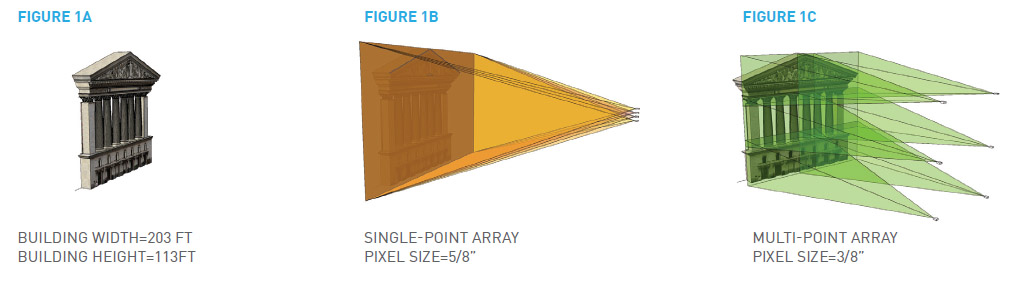
The primary factors to analyze include brightness, resolution, orientation and quantity of projectors. There are two basic approaches – single and multiple raster. The single raster approach uses a single projection point to address the entire image area – top to bottom, left to right. Additional projectors are then overlaid and converged to add brightness until a level is achieved that will work successfully in the given environment (See Fig. 1b). This approach requires careful alignment of the converged projectors but eliminates the complexity of edge-blending required by multiple raster configurations.
Using the more complicated multiple-raster or “tiled” approach provides higher image resolution by creating an array of projected images that are knit together to create a single image area (See Fig. 1c). This approach is more complicated than the single-raster approach because it requires soft-edge masking of overlapping images but is made easier by the comprehensive features available within Panasonic projectors.
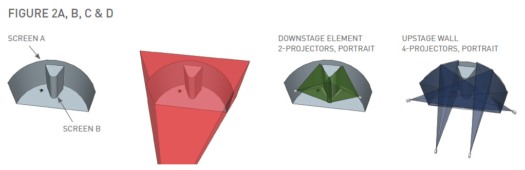
Using Fig. 2 as an example, we see a curved screen measuring 10m tall with an arc length of 27.664m and radius of 10.25m (Screen A). Inset within the curved screen is a triangular protrusion to add a level of complication (Screen B). Of course, it would be theoretically possible to utilize a single projector position to cover this entire area (Fig. 2a) but this approach would be severely compromised and would almost certainly result in a dim, fuzzy image with visible shadow areas, so we’ll proceed directly to a multi projector array approach. For this example, we’ll also assume that none of the image surfaces move, so we’ll avoid the added complication of motion tracking that would be addressed by a movement sensing system feeding data to image warp processors.
To begin, look for image areas that correspond with standard aspect ratios but don’t limit your thinking to landscape orientation as Panasonic’s SOLID SHINE™ laser projectors can easily be rotated 90-degrees to create a portrait image. In Fig. 2c, there are two projectors to address Screen B. These are in portrait orientation and positioned on-axis to the primary surfaces of the element to retain sharpness and brightness. The downstage curved or “bull-nose” portion of the object will be addressed with overlap between the two projectors.
In Fig. 2d, four additional projectors in portrait orientation have been added to address Screen A. Notice how they are splayed to remain, more or less, on-axis to the screen surface. Also notice how the center projectors are placed to allow the image to carry behind the downstage scenic element. For an actual show, these six projectors would be duplicated for redundancy and additional brightness (dual-converged) bringing the total projector compliment to twelve.
With the raster sizes depicted in this example (approximately 68.9 sq meter) a 21,000 lumen projector, such as the Panasonic PT-RZ21KU, would result in 300 lux or 30 foot-candles of light at a 1 gain screen surface. Assuming dual-converged projectors for redundancy and additional brightness, the projected light doubles to 600 lux or a 50% increase in “perceived” brightness perfectly adequate for a stage backdrop in a controlled lighting environment. Of course, an even brighter projector, such as the Panasonic PT-RZ31KU with 30,000 lumen output, will provide even more impactful imagery.
In all cases, a clear understanding of the ambient light levels in a particular environment is a key factor when calculating the effective brightness and contrast of the projected image. For brighter environments, such as a trade show floor, the ight level described above will likely be insufficient and be overwhelmed by ambient light. Studying the architectural guidelines for various types of environments (offices, city streets, retail) can provide useful information or, if in doubt, grab a light meter and make a site visit.
The other significant brightness factor is the image surface to be used, which might be masonry, glass, fabric or metal and may decrease brightness (negative gain) or lack diffusion characteristics (create hot spots). The best method for determining this factor is to view the image surface first hand and observe how it reflects light. If faced with a really unusual surface material, a test with a projector may be required to understand the reflectance properties.
In terms of image resolution, larger image sizes require higher resolution projectors to provide sharp, crisp images. 4K+ projectors, such as the Panasonic PT-RQ32KU, will provide additional image detail and clarity, compared to WUXGA or HD projectors, that will be noticed by even the untrained eye once raster sizes exceed 10m wide. On smaller screens, the 4K+ models also provide benefit when the viewing distances are short, as the visible pixel remains hard to detect even from an arm’s length away from the image surface.
SELECTING THE BEST PROJECTION LENS FOR THE PROJECTOR CONFIGURATION
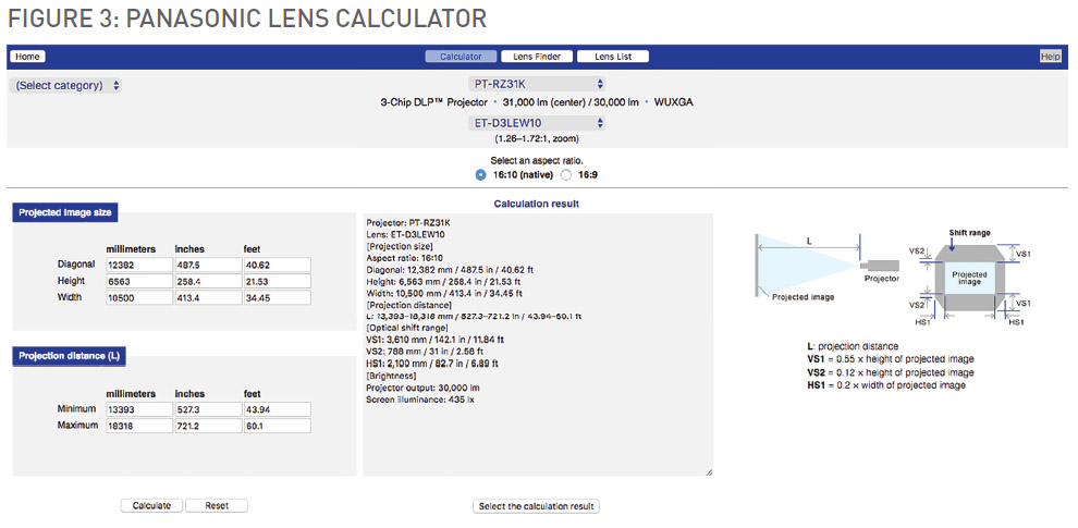
Projector positions and coverage possibilities are determined by the available lenses and Panasonic’s on-line Throw Distance Calculator is an excellent tool for checking lens options (See Fig. 3). In this example, a medium zoom lens has been selected, providing a wide range of location and lens shift options. However, it might be useful to research one of Panasonic's wide lens option, such as the ET-D75LE6 wide zoom, which would allow the projectors to be located close to the screen surface or object and provide a steep projection angle allowing more movement on the stage with minimal shadowing.
UTILIZING PLANNING TOOLS
3D CAD: The ubiquity of 3D CAD programs has been a boon to projection mapping designers, allowing them to easily lay out projectors and objects in an accurate 3D environment. Whether created in Vectorworks, AutoCAD, Sketchup, Blender or another application, the environment should include accurate representations of the projectors being used as well as image sizes, throw distances and lens shift tolerances pulled from the manufacturer’s lens calculator program.
However, before an accurate 3D of the project can be created, there must be an accurate 3D CAD model of the object that is being mapped. In some situations such as when the object is being fabricated or if an architectural 3D model is available, these can be converted for use in a 3D CAD program of your choice. In other cases, it may be necessary to hire a company specializing in 3D laser scanning (using a “LIDAR” device). These folks will come to the site and scan the environment, and then compile the data into a cloud-point model that can be ingested into a 3D CAD environment. This process is not terribly expensive and provides extremely accurate results.
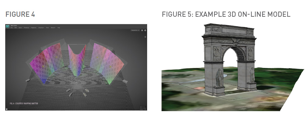
GEO-LOCATION: For outdoor projects, particularly building projects, on-line mapping programs can provide a wealth of data that can be used for planning. In fact, there are many buildings available in simple 3D that are available on-line for free if you use certain applications (see Fig. 5). While these do not substitute for a hands-on site survey, they are often close enough for budgeting and feasibility purposes.
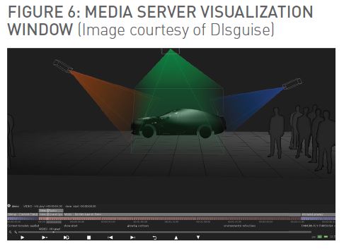
PHOTO RENDERS: For clients that need to see a photo-accurate rendering of the project, the best approach is to use a graphic artist with experience building photo-realistic images. This type of rendering will show representative environmental lighting conditions as well as surface textures and still images of the intended video content.
MEDIA SERVER-DRIVEN PRE-VISUALIZATION: If the project is using a media server for content playback and programming, the media server platform may support 3D visualization (See Fig. 6). This type of visualization can be a very powerful tool with “fly-through” capability, accurate resolution depiction and an indication of brightness uniformity, or the lack thereof. Further, on some systems it is possible to port the visualization into a VR system, providing an interactive immersive view of the project.
CREATING THE CONTENT TEMPLATE
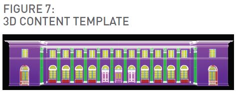
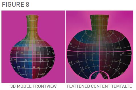
Since projection mapping projects are inherently nonstandard, content creators need guidelines for producing content that will properly fit the projection areas (see Fig. 7 where different surfaces are denoted by color). If the mapping is complex with significant depth to the physical surface, such as the vase in the example, the 3D surfaces may need to be “flattened” or UV mapped (See Fig. 8) in order to create content that can be mapped to the object. For very complex mapping projects it is best that the content creator and media server programmer work closely using the same 3D objects and mapping tools. This may avoid the need for UV maps as the content creators map textures directly to the 3D objects
in a virtual 3D environment. However, this choice is up to the content creator and determined by their work flow.
IN THE SHOP
ESSENTIAL ITEMS
An indoor projection mapping project does not require anything that wouldn’t be included in a well-planned stage event. However, outdoor mapping projects come with significant overhead in terms of additional requirements. Some of the items to consider are:
Pop-up tent – To be used for weather-proofing the control and production area. Should be heated in cold weather, air-conditioned or, at the very least, fan-cooled in warm weather.
Projector enclosures – These can range from purpose built enclosures designed to protect and ventilate
specific projector models, to standard production scaffold with a tarpaulin roof. For productions that require performance in any type of weather, the projector enclosure or a well-built weather-proof structure is the preferred method. Note that most current-model projectors do not rely on cooled air to function but do require significant air flow volume. Therefore, air conditioning is not likely to be required but forced air at significant levels will most certainly be needed.
Cable Infrastructure and Support – Large outdoor projection mapping projects require a great deal of
power and signal cabling because projector locations and the control area location may be spread out over a large geographic area. Most system engineers will opt for fiber-optic cable for signal and control, passing either DVI/HDMI or 3G SDI through the cable system and fiber-optic converters. For most of these applications, 3G SDI provides a more reliable signal format. As important are items such as cable ramps, tie-downs and boom and base to create cable path goal posts or other methods for keep cable and humans out of each other’s way.
PLANNING FOR REDUNDANCY
If the mapping system is relying on media servers to provide content and geometry correction, these systems should be designed to be fully-redundant with a 100%-reliable fail-over method. These systems are computers and computers crash usually at the least opportune time, so a system that allows the operator to switch to back-up reliably and quickly is critical. Panasonic projectors, which incorporate an auto input switch capability that can switch to a back-up input within 0.3 seconds, is a great option for creating redundant signal paths. On the other hand, projectors have become more and
more reliable over time and with the advent of solid state light sources, such as the Panasonic SOLID SHINE™ laser projectors, reliability in the field is outstanding. This decreases the need for projector redundancy and for many projects, a single “cold” spare, provides an adequate level of safety.
STAFFING
Staffing levels for projection mapping projects are different than more conventional projection projects as the technicians responsible for installing and aligning the projectors have a lot more to get done prior to show, particularly if they are utilizing projection mapping features in the projectors versus a media server. Therefore, a plan that populates the show schedule with enough projection techs to ensure that every projector is fully commissioned and aligned within the given
schedule is strongly recommended.
PRE-PROGRAMMING
If the mapping project is utilizing media servers with visualization capability, working in a virtual environment allows the programmer to “pre-program” the show, creating cues as well as the all-important warp mesh, which is the geometry correction map required to warp the image to the 3D surface. This process can save a great deal of time on site as well as dampen a lot of anxiety. This part of the process should also be used to pre-test content, making sure that it encodes properly and play without noticeable artifacts such as stutter, frame drops or aliasing errors. Most media servers are picky, in terms of the CODECs employed to compress content, so build in a period of trial and error to ensure that the final content looks as good as possible when projected.
IN THE FIELD
SCHEDULING THE AVAILABLE TIME
Whether a mapping project is indoors or outdoors can affect the work schedule significantly, since in the outdoors, the project is subject to daylight and daylight makes it impossible to align projectors. Therefore, the project schedule should include as many overnights as required to allow the projection technicians adequate time to install, align and commission projectors. On a very large project with many projectors and complicated mapping, this could be as many as three or four nights.
An indoor project will likely have a less restrictive schedule but often it makes the most sense to schedule intensive projector alignment during overnights when the event is free of other activity and the projection technicians can concentrate on the work at hand in a quiet, dark environment.
USING PROJECTOR FEATURES
Projectors designed by Panasonic for large-venue work include a set of features making them ideal for complex mapping projects. These features include comprehensive geometry correction software that works in tandem with an auto screen adjustment feature, making complex alignment work a fast, automated process.
Using the Panasonic ET-CUK10 Auto Screen Adjustment accessory software license and a Nikon DSLR camera1 (youtu.be/p1WpVl8tdVQ), it is now possible to set-up an auto-alignment system that can greatly reduce the time required to align a projection mapping system, particularly on more standardized screen shapes such as curves. The software also supports advanced manual geometry alignment based on a user-defined grid and matrix point.
While similar features may exist in media server platforms and, at first glance, may seem duplicative, having this feature set in the projector provides an added level of control that is extremely useful as the media server programmers and projection technicians work together to create tight, accurate adjustments. In situations where the content playback system has limited or no warping capability, the Panasonic system can provide stand-alone capability for even the most complex geometry correction requirements. Having used the projector geometry controls to create a warp map and having applied the map to the projector(s), the next part of the process is making sure any multi-projector arrays are properly balanced for color, brightness and that the blend or overlap areas are as invisible as possible. Using the advanced blending properties of Panasonic’s large-venue projectors, technicians will find menu features allowing them to quickly create accurate color uniformity and the all-important black-level blending. The result should be overlap areas that are almost invisible no matter the type of content displayed.
Bear in mind that the power of the ET-CUK10 feature set, along with many other projector features cannot be utilized properly unless the projectors are connected to a reliable Ethernet network. In other words, the days of pointing a projector remote up in the air are over and all projection technicians on projection mapping projects should be utilizing the networked control functionality provided by Panasonic projectors.
The network control applications provide full-control of all the projectors within the network, duplicating all the features listed in the projector menus but providing a much richer user interface. Single projectors or groups of projectors can be controlled and, if the network has WiFi access, the technicians can roam the work environment finding ideal viewpoints to observe their work.
SHOW TIME!
The power, reliability and flexibility of Panasonic projectors can propel even the most complicated mapping project to show time with a minimum level of stress, effort and anxiety. Then, once the show begins, the technicians can sit back and monitor the projection system remotely and even make adjustments on the fly through the networked control system. From the viewer perspective, the visuals will be crisp and bright with accurate colorimetry and, should the projectors be located in the audience area, the low-noise output of the Panasonic SOLID SHINE™ laser projectors will not intrude on their enjoyment of the sound elements.
With proper planning, good team work within the design and production staffs, and state-of-the-art projectors from Panasonic, no projection mapping project should be deemed impossible.